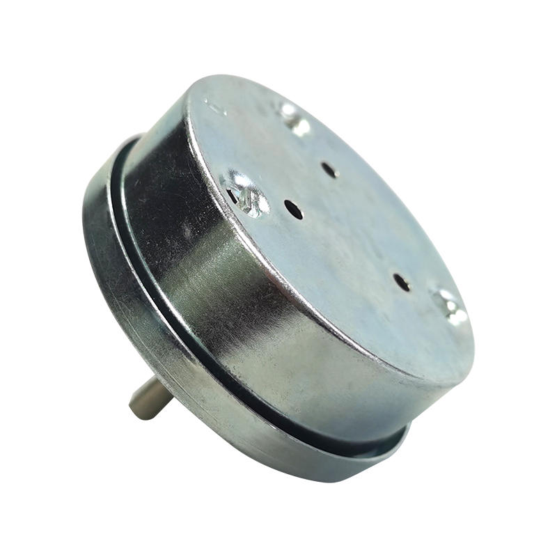
Home / News / Industry News / What Makes a Small Size Precision Mechanical Timer Reliable?
What Makes a Small Size Precision Mechanical Timer Reliable?
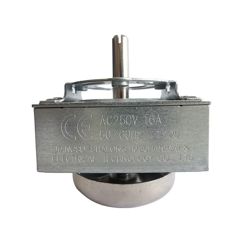
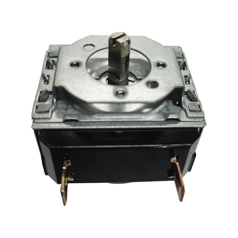
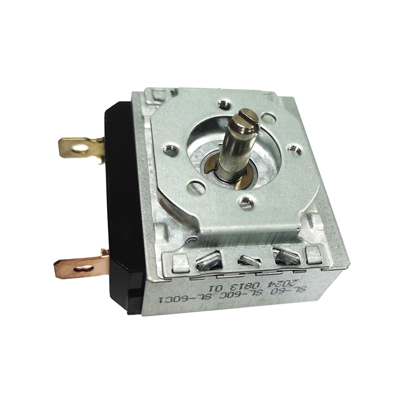
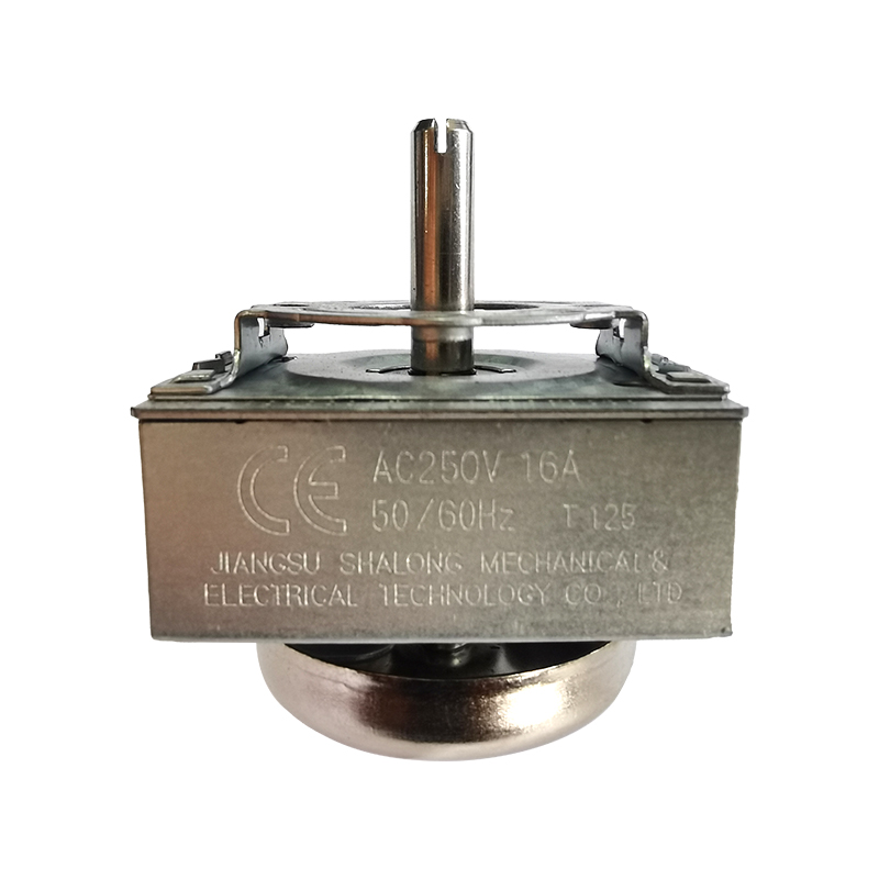
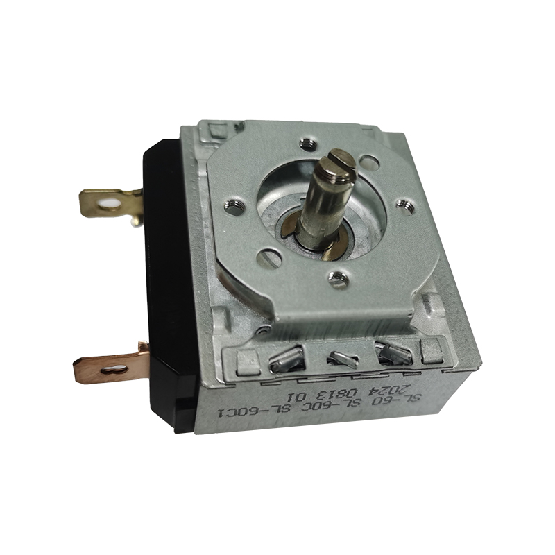
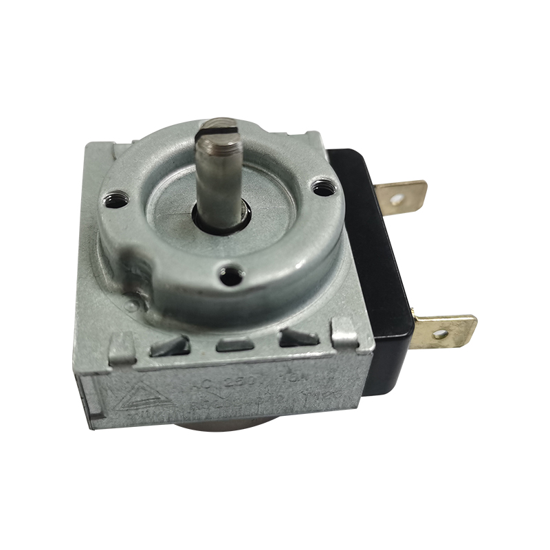
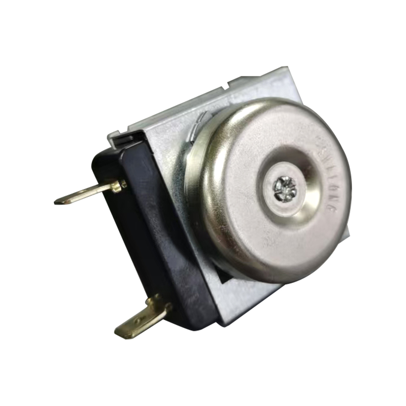
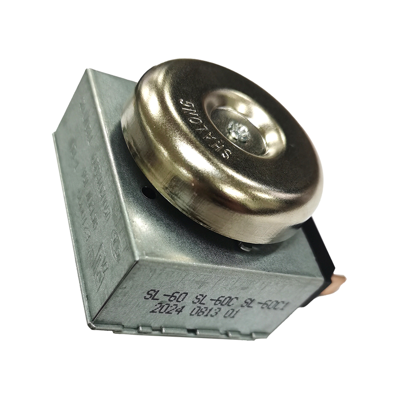
A Small Size Precision Mechanical Timer is a compact, spring-or-motor-driven timing device that uses gears, cams, and a switch mechanism to control the on/off cycle of an electrical circuit without relying on digital electronics. In short, this type of timer is chosen when an application needs a physically small footprint, dependable mechanical switching, and stable performance in environments where heat, vibration, or voltage fluctuation would challenge sensitive digital components. Because the mechanism is entirely mechanical, it tends to remain functional after years of repeated use, which is one of the main reasons appliance manufacturers and industrial equipment builders continue to specify this category of component. The remainder of this article walks through how these timers work, how to read their instructions and manual documentation, where they are used, and how they compare with other timing technologies, supported by data visualizations and a technical overview of the internal structure.
What Defines a Small Size Precision Mechanical Timer
At its core, a small size precision mechanical timer consists of a synchronous or spring-wound drive motor, a reduction gear train, a cam or dial mechanism, and one or more switch contacts. The drive motor turns at a fixed, known speed, and the gear train reduces that speed into a usable timing range, whether it is a few seconds or several hours. As the cam rotates, it physically pushes against the switch contact at the pre-set position, opening or closing the circuit at the moment the user selected. Precision in this context refers to the tightness of the tolerance between the dial setting and the actual switching point, which is typically achieved through fine gear ratios, hardened metal components, and careful factory calibration.
Compact housings are achieved by using small-modulus gears and dense internal layouts, which is why the manufacturing process for these components often requires specialized hobbing and stamping equipment rather than generic off-the-shelf parts. Analog Timers of this class are frequently rated for use inside household appliances such as rice cookers, bread machines, and air fryers, as well as in light industrial control panels. The following table summarizes the general characteristics that distinguish a small size precision mechanical timer from a standard-size electromechanical timer.
General comparison of timer categories by typical construction characteristics
Characteristic
Small Size Precision Mechanical Timer
Standard Electromechanical Timer
Footprint
Compact, space-saving
Larger housing
Typical use case
Small appliances, circuit boards
Industrial panels, large equipment
Gear construction
Small-modulus precision gears
Standard modulus gears
Heat tolerance focus
Often engineered for elevated temperatures
Varies by model
Mechanical Timer Adoption Across Industrial Applications
Before looking at the chart below, it helps to understand why adoption data matters for buyers of Analog Timers and small size precision mechanical timer components. Purchasing teams often want to know whether a timing technology is still actively specified in current designs, or whether it is being phased out in favor of digital alternatives. Adoption figures collected from industrial automation surveys give a practical signal of where mechanical and electromechanical timers remain the preferred choice. This is particularly relevant for engineers selecting components for HVAC systems, conveyor controls, and motor-cycling applications, where robustness under electrical noise and vibration is often valued over programmable flexibility. The horizontal bar chart below presents adoption rates reported for DIN-rail mounted timers, a mounting format closely related to the small, precision timer category discussed in this article.
According to industry market research on the analog timer segment, roughly 60 percent of programmable timers deployed on factory floors use DIN-rail mount formats with adjustable ranges spanning from a fraction of a second up to several hours, making them well suited for conveyor belts, motor controls, and pump cycling tasks. In HVAC applications, just over half of controllers, about 55 percent, rely on DIN-rail timers to manage fan and compressor cycling within short interval windows. This tells us that mechanical and electromechanical timing formats remain a mainstream choice rather than a legacy technology limited to older equipment. The gap between the two segments is relatively small, which suggests that timer selection criteria are similar across both factory automation and building climate control contexts. Buyers researching a small size precision mechanical timer manual or instructions for integration should note that many of these installations still favor manually adjustable, visually inspectable timing mechanisms over fully digital replacements. This preference is often tied to maintenance simplicity, since a technician can visually confirm a cam position or dial setting without a diagnostic laptop. It also reflects the reality that many control panels are designed to tolerate power surges and electrical noise that can be disruptive to unshielded digital circuitry. For OEM design teams, this data supports the case for continuing to specify compact mechanical timer components in updated product lines rather than assuming a full digital transition is required. The chart above should be read as a general industry indicator rather than a guarantee of adoption in any specific end product. Readers should always confirm technical requirements against the actual datasheet of the component being considered for a project.
Reading the Small Size Precision Mechanical Timer Instructions and Manual
Small size precision mechanical timer instructions typically follow a similar sequence regardless of the specific application, whether the component is being wired into a rice cooker, a bread machine, or an industrial control panel. Understanding this sequence in advance makes it easier to interpret a small size precision mechanical timer manual quickly, without needing to contact technical support for routine installation questions. Below is a general step-by-step outline that mirrors the structure found in most manufacturer documentation for this component category.
Confirm the rated voltage, current, and temperature range printed on the timer housing against the application requirements before wiring.
Identify the terminal layout using the wiring diagram included in the manual, noting which terminals correspond to the common, normally open, and normally closed contacts.
Mount the timer securely using the panel cutout or screw pattern specified, ensuring the dial or knob remains accessible for the end user.
Connect the wiring according to the diagram, double-checking polarity and load requirements for the connected circuit.
Rotate the dial to a short test interval and verify that the switch actuates at the expected point before final assembly.
Record the calibration reference position noted in the manual, which is useful if recalibration is ever required during maintenance.
Manuals for this component category also typically include a maintenance section, since mechanical parts benefit from periodic inspection even though they do not require the firmware updates associated with digital timers. Common maintenance guidance includes checking for gear wear after extended use, keeping the mechanism free of dust or moisture, and avoiding excessive torque when manually adjusting the dial. Manufacturers usually specify an expected operating temperature range in the instructions, which is especially important for a small size precision mechanical timer being installed near a heat source such as a cooking appliance motor or an oven control panel. Reading this section carefully before installation reduces the likelihood of premature component failure and supports a longer effective service life.
Market Growth Trend for Mechanical and Electromechanical Timers
Understanding the growth trajectory of the mechanical timer category helps explain why manufacturers continue to invest in this technology rather than discontinuing it in favor of purely digital alternatives. Industry research tracking the broader mechanical timer market has projected continued expansion driven largely by demand from kitchen appliances and industrial equipment segments. This trend line matters to specifiers of a small size precision mechanical timer because a growing market typically supports continued component availability, ongoing engineering investment, and stable long-term sourcing. The line chart below illustrates the general upward growth pattern reported for this market segment between 2024 and 2031. This is presented as an illustrative trend line reflecting the reported compound annual growth rate rather than an exact year-by-year dataset.
Market research covering the mechanical timer category has reported a projected compound annual growth rate near 5.2 percent from 2024 through 2031, with growth attributed largely to sustained demand in kitchen appliance and industrial equipment segments. This steady upward trend suggests that the mechanical timer is not a fading technology but rather one that continues to find new applications alongside digital alternatives. The consistency of the growth curve, rather than sharp spikes, indicates demand driven by routine appliance production cycles instead of speculative or short-term factors. For component buyers, a stable growth trend is generally a positive signal, since it points toward continued investment by manufacturers in tooling, quality control, and supply reliability. It also suggests that engineering support and spare part availability are likely to remain accessible for years to come, which matters when designing a product with a multi-year production lifecycle. Readers should treat this chart as a general market direction indicator rather than a precise forecast for any single manufacturer or product line. Actual results can vary by region, appliance category, and the pace at which digital alternatives are adopted in specific markets. Even so, the overall direction supports the continued relevance of small size precision mechanical timer components in both consumer and industrial product design. This is a useful data point for engineers weighing long-term component strategy against short-term cost or feature considerations. It also explains why specialized manufacturers continue to develop new tooling and gear designs specifically for this component category rather than treating it as a legacy product line.
Where Small Size Precision Mechanical Timers Are Used
Before reviewing the distribution chart in this section, it is worth outlining the general categories of equipment that rely on small size precision mechanical timers in day-to-day operation. These components appear most commonly in household and small commercial appliances where a compact, low-cost, and reliable timing function is needed without the complexity of a digital control board. They are also used inside larger appliance control assemblies as a supporting component alongside other circuit board elements. Industrial equipment manufacturers use related electromechanical timer formats for motor cycling, lubrication systems, and program temperature controls. The chart below presents an illustrative distribution of where this general category of timer tends to be applied, based on patterns commonly described across industry sources rather than a single statistically weighted survey.
Home appliances represent the largest single application category for this type of timer, covering products such as rice cookers, bread machines, air fryers, and other small kitchen equipment where a compact and heat-tolerant timing mechanism is required. Industrial equipment forms the second largest segment, including motor control, lubrication systems, and program temperature controls where electromechanical timers provide dependable cycling without the need for constant software maintenance. HVAC systems and lighting controls make up a meaningful portion of remaining demand, where timers manage fan cycles, compressor intervals, and scheduled lighting operation. A smaller remaining share covers a variety of other uses, including laboratory equipment, food service devices, and specialty consumer products. This distribution is consistent with how industry sources describe electromechanical timers being used across appliance, food service, commercial, and industrial applications. The concentration of demand in home appliances explains why manufacturers place significant emphasis on compact size and high-temperature tolerance, since these products are frequently mounted close to heating elements or motor assemblies. It also explains why circuit board integration capability matters for many buyers, since appliance manufacturers often want the timer to interface directly with an existing control board rather than functioning as a fully separate unit. This chart should be interpreted as a general directional illustration of where the technology is applied rather than a precise market share study. Engineers selecting a component for a new design should still confirm suitability against their own application requirements rather than relying solely on general industry patterns. Even so, the broad pattern shown here is useful context for understanding why this timer category continues to be specified across such a wide range of product types.
Sourcing Considerations: Mechanical Timer Made in USA and Global Manufacturing Options
Buyers researching a mechanical timer made in usa are usually trying to solve for a specific set of priorities, including supply chain traceability, familiar technical support channels, and confidence in documentation quality. These are legitimate priorities, and they are worth addressing directly rather than avoided. What matters most in practice is not simply where a component is assembled, but whether the manufacturer maintains its own tooling, in-house engineering capability, and consistent quality control processes across production runs. A facility that designs and builds its own gear-cutting equipment, stamping molds, and testing apparatus is generally able to maintain tighter tolerances than one that outsources core manufacturing steps to third parties, regardless of the country involved.
What to Evaluate Beyond Country of Origin
When comparing sourcing options, it is more productive to evaluate the depth of engineering resources, the availability of technical documentation such as a small size precision mechanical timer manual, and whether the supplier holds relevant industry certifications or has contributed to drafting technical standards for the product category. Manufacturers that have been producing timing mechanisms for multiple decades typically accumulate practical process knowledge that is difficult to replicate quickly, regardless of geography. Buyers should also confirm whether a supplier performs in-house testing for temperature resistance, mechanical cycle life, and electrical rating verification, since these steps directly affect the long-term reliability of the finished component. Requesting sample units and reviewing full technical drawings before committing to a production order remains one of the most reliable ways to validate supplier capability, whichever country the component is manufactured in.
Understanding Precision Calibration in Mechanical Timer Mechanisms
Calibration confidence is one of the more abstract but important qualities to understand when evaluating a small size precision mechanical timer, since it directly affects how closely the actual switching point matches the dial setting selected by the user. The gauge chart below is a conceptual illustration intended to help readers visualize the relationship between manufacturing tolerance and calibration reliability, rather than representing a specific measured certification value for any single product. It draws on general engineering principles related to gear train precision and cam design rather than a numeric test result. Readers evaluating a specific component should always request the manufacturer's actual test data rather than relying on a general illustration. With that context established, the visual below outlines the factors that influence where a given timer mechanism sits along this conceptual reliability spectrum.
The position of the needle in a diagram like this one is meant to represent the general idea that tighter manufacturing tolerances lead to higher calibration confidence, while wider tolerances introduce more variance between the dial setting and the actual switching point. Several practical factors influence where an actual product would fall along this spectrum, including the modulus and material of the gears, the precision of the stamping molds used to form internal components, and the consistency of the factory calibration process applied before shipment. Small-modulus gear systems, when manufactured with dedicated hobbing equipment, tend to support tighter tolerances than components built on generalized, shared tooling. Metal gear trains generally maintain their calibration over more duty cycles than plastic alternatives, particularly in applications involving elevated ambient temperatures near heating elements or motors. Automated inspection during production, rather than manual spot-checking alone, also contributes meaningfully to consistent calibration across a full production batch. For engineers, this means that questions worth asking a supplier include what tooling is used internally, whether inspection equipment is calibrated and maintained on a regular schedule, and what tolerance range is guaranteed in the technical specification sheet. It also means that a small size precision mechanical timer intended for high-temperature-adjacent applications should be evaluated specifically for tolerance stability under thermal load, not only under standard room-temperature test conditions. Buyers should request this information directly from the manufacturer's engineering documentation rather than relying on general marketing claims. This concept chart is intended purely as an educational aid to frame that conversation, not as a substitute for actual test reports. Readers making a purchasing decision should always base their final judgment on verified technical data provided by the supplier for the specific part number under consideration.
Internal Structure of a Small Size Precision Mechanical Timer
Understanding the internal layout of a small size precision mechanical timer makes it easier to interpret both the instructions and the manual provided by a manufacturer, since most documentation refers back to these core components by name. The schematic below is a simplified, labeled isometric-style illustration showing the general arrangement of a typical unit, including the housing, dial, gear train, cam, and switch terminals. It is intended as an educational diagram rather than an exact rendering of any single part number.
The dial or setting knob sits on the outer face of the housing and connects to the gear train through a central shaft, allowing the user to select the desired timing interval. Turning the dial physically winds or positions the internal cam, which is the component responsible for tracking elapsed time as the mechanism runs. The gear train reduces the speed of the drive motor into a usable timing range, and the precision of these gears is what allows a small size precision mechanical timer to maintain accuracy across its rated interval. The cam mechanism rotates in coordination with the gear train and is shaped so that, at the pre-set position, it physically actuates the switch terminal, opening or closing the connected circuit. Switch terminals are typically accessible from the rear of the housing and are wired according to the diagram provided in the manual, with clear labeling for common, normally open, and normally closed connections. This general layout remains consistent across most small size precision mechanical timer designs, even though exact dimensions and terminal counts vary by model and application. Recognizing these components on sight makes it considerably easier to troubleshoot an installation issue or interpret a wiring diagram without needing to contact technical support for basic questions. It is also useful background knowledge when comparing technical drawings between different suppliers during a sourcing evaluation.
About the Manufacturer
Jiangsu Shalong Mechanical & Electrical Technology Co., Ltd. was founded in 1991 and has operated as a professional manufacturer of high-temperature-resistant metal mechanical timers for more than three decades, participating as a drafting unit for relevant industry standards along the way. The company specializes in the research, development, production, and sales of mechanical timers along with household appliance circuit board products, combining long-term practical accumulation with ongoing technological innovation.
The facility is located along the Yangtze River in the Jingjiang Economic and Technological Development Park, operating with a registered capital of 28 million yuan across more than 40,000 square meters of self-built factory space. Production and quality assurance are supported by over 1,000 sets of research, production, and inspection equipment, staffed by more than 800 employees, including over 80 engineering and technical personnel. Notably, the small-modulus hobbing machines, automated processing equipment, and high-speed continuous stamping molds used in timer production are independently developed and manufactured in-house, supported by several technical patents, which allows for tighter control over dimensional consistency and calibration accuracy across production runs.
This combination of dedicated tooling and full-range testing equipment has supported long-term cooperative relationships with well-known appliance manufacturers, and the company's products are exported to international markets including South Korea, Turkey, Brazil, Saudi Arabia, and Egypt, reflecting a manufacturing footprint built for global supply requirements.
Frequently Asked Questions
Q1: What makes a timer qualify as a small size precision mechanical timer? It is defined by a compact housing, fine gear ratios for accurate timing, and a fully mechanical switching mechanism rather than digital electronics, making it suitable for space-constrained appliance and circuit board applications.
Q2: Where can I find small size precision mechanical timer instructions for a new installation? Instructions are typically included with the component and cover terminal wiring, mounting dimensions, and test procedures; manufacturers can also provide the full manual directly upon request for a specific part number.
Q3: Are Analog Timers still relevant compared to digital timing solutions? Yes, analog and electromechanical timers remain widely used in appliances and industrial equipment due to their mechanical reliability, resistance to electrical noise, and ease of visual inspection during maintenance.
Q4: What should I compare when sourcing between a mechanical timer made in usa and other manufacturing origins? Focus on in-house tooling capability, testing procedures, documentation quality, and long-term production experience rather than country of origin alone, since these factors have a more direct impact on product consistency.
Time setting: 15', 20', 30', 60' or customized (such as 90 min)Applicable: Oven/Electric Pressure Cooker/Kitchen MachineContact capacity: AC 120V 15A;...
Time setting: 15', 20', 30', 60' or customized (such as 90 min)Applicable: Oven/Electric Pressure Cooker/Kitchen MachineContact capacity: AC 120V 15A;...
Time setting: 15', 20', 30', 60' or customized (such as 90 min)Applicable: Oven/Electric Pressure Cooker/Kitchen MachineContact capacity: AC 120V 15A;...
Time setting: 15', 20', 30', 60' or customized (such as 90 min)Applicable: Oven/Electric Pressure Cooker/Kitchen MachineContact capacity: AC 120V 15A;...



 English
 中文简体
中文简体