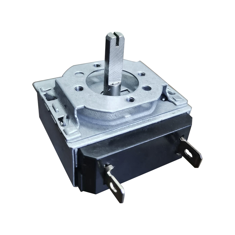
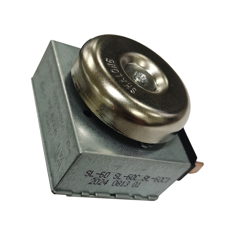
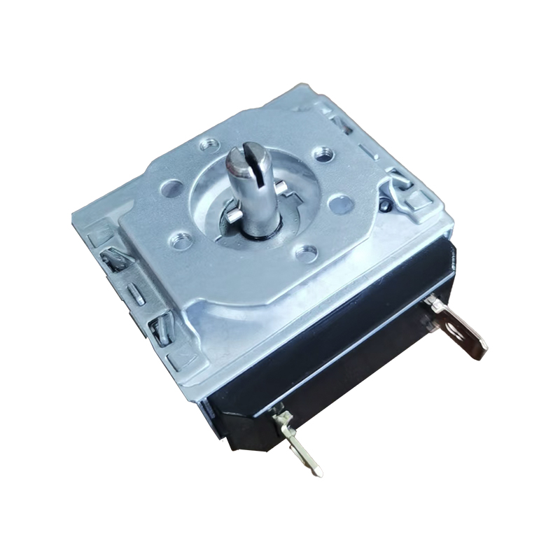
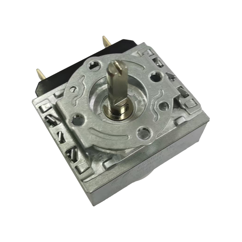
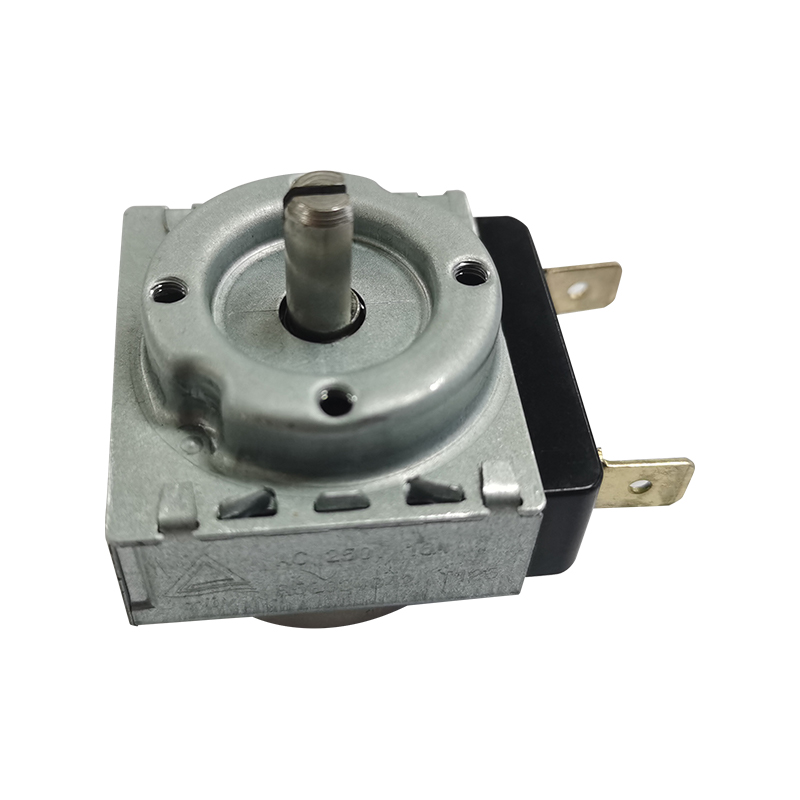
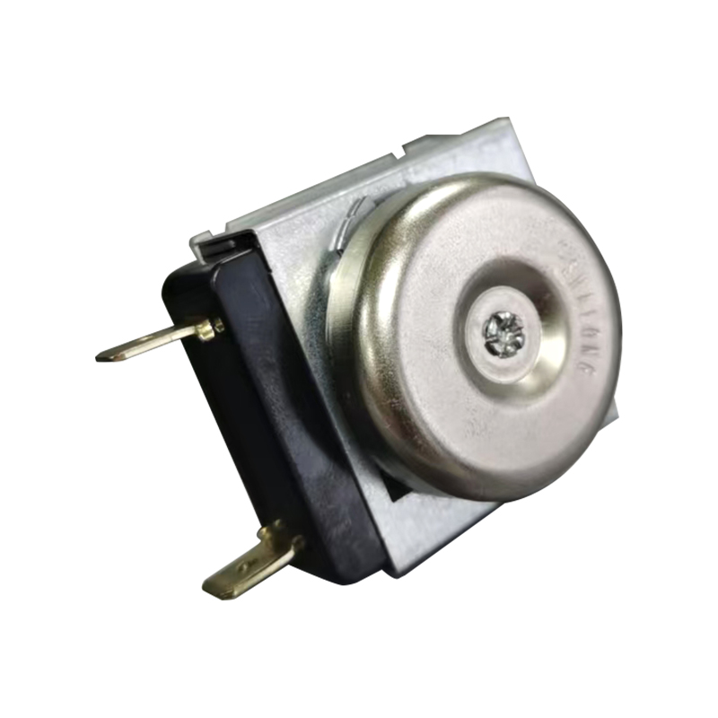
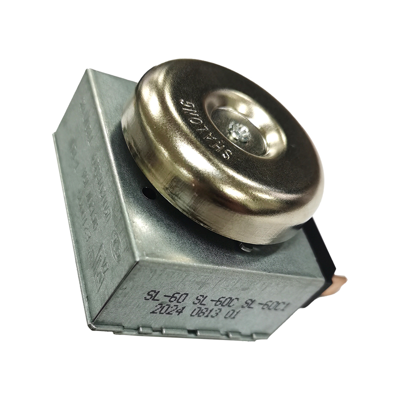
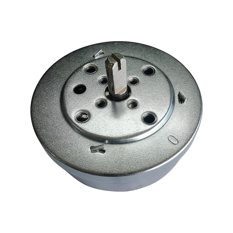
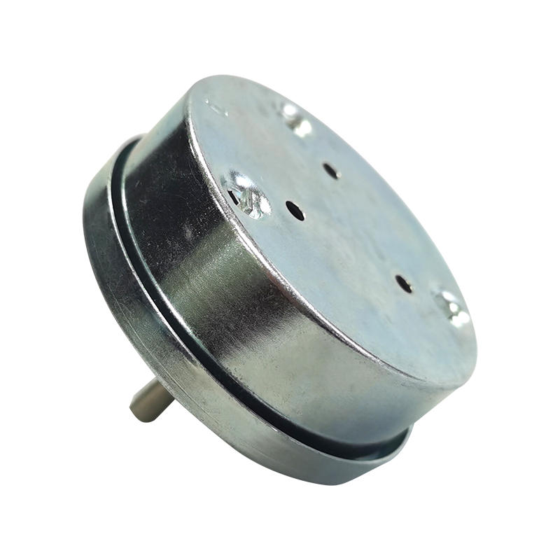
To set time on a mechanical timer, locate the central time-setting dial or knob on the face of the unit, turn it in the direction marked on the dial (most household and appliance timers turn clockwise), and align the pointer or index mark with the current time or the desired countdown interval. On most spring-driven or geared timers, a light click or a small amount of resistance from the internal gear train confirms that the setting mechanism has properly engaged. The core action is always the same across most designs: rotate the dial until the marker reaches the correct position, then release it gently rather than forcing it past its stop point. This guide walks through the mechanism behind that action, compares how different mechanical timer types are set, and reviews accuracy and reliability data so the process makes sense rather than being a memorized routine.
A short version of the process looks like this:
Identify the setting dial, knob, or slider and confirm the direction of rotation printed on the housing.
Turn the dial slowly toward the desired time or countdown value, watching the pointer rather than turning by feel alone.
Stop turning once the marker aligns with the target position, avoiding force against the mechanical stop at either end of the dial.
Release the dial and observe that it holds its position without drifting, which indicates the gear train has seated correctly.
For timers with a separate start or hold switch, activate that control only after the time value has been set.
These steps apply broadly, but the exact setting method differs between a basic spring-wound dial timer, a geared synchronous timer, a programmable mechanical timer, and a high-temperature-resistant industrial timer. The sections below compare these timer types in detail, including how their internal mechanisms affect setting accuracy and long-term reliability.
Understanding How a Mechanical Timer Measures Time
A mechanical timer converts a manually set position into a controlled, repeatable sequence of movement using a small number of interacting parts: a mainspring or motor-driven input, a gear train that reduces speed and multiplies torque, a time-setting dial connected to that gear train, and one or more electrical contact points that open or close a circuit at the moment the dial reaches zero or a preset mark. Setting the time is mechanically the act of repositioning the gear train relative to the contact mechanism, not simply moving a decorative pointer. When the dial is turned, the internal gears rotate in proportion to the distance turned, storing that rotational position until the timer is allowed to run down or the motor drives it back toward zero. This is why forcing a dial past its mechanical stop, or turning it in the wrong direction, can misalign the gear train and cause inaccurate timing or a contact point that never triggers.
The illustration below shows a generic isometric view of a mechanical timer housing, with the main functional areas labeled. It is a schematic representation rather than a photograph of a specific product, intended to show where the setting dial, gear train, mainspring, and contact terminals are typically located relative to one another.
Figure 1. Schematic isometric view of a mechanical timer housing, labeled by functional area.
In the diagram, the dial sits on the top face and connects directly to the gear train shown on the internal left face, which is the same gear train that a small modulus hobbing machine cuts during manufacturing. The mainspring, drawn as a coiled internal element, stores the mechanical energy that drives the gear train forward once the timer is set and released. The contact terminals on the right face are where the electrical circuit is physically opened or closed, so any dirt, corrosion, or misalignment at that point can cause a timer to appear correctly set while still failing to trigger the connected appliance. The housing itself, particularly in high-temperature-resistant designs, is built to keep this internal geometry stable even when the surrounding appliance compartment reaches elevated operating temperatures. Because every one of these parts is mechanically linked, setting the time correctly is really about positioning the whole gear train, not just moving a dial that looks like it points somewhere sensible.
Many geared mechanical timers also include a small escapement or governor element, a component that regulates how quickly stored energy from the mainspring or motor is released so that the dial counts down at a steady, predictable rate rather than all at once. This is functionally similar in concept to the escapement found in mechanical clocks, though simplified for a single countdown or scheduling function rather than continuous timekeeping. The electrical contact point, where the circuit is actually opened or closed, is typically the component that wears fastest because it experiences both mechanical movement and electrical arcing each time it switches, which is why a timer that turns smoothly by hand can still fail to trigger a connected appliance if that contact surface has become pitted or oxidized. Manufacturers address this by selecting contact materials and geometries rated for the expected switching current and cycle count of the target application, rather than using a single generic contact design across every product line. Understanding this distinction, that the dial mechanism and the contact mechanism are related but separate failure points, is useful when diagnosing a timer that seems to set correctly but does not reliably start or stop the appliance it controls.
How Operating Temperature Affects Timer Setting and Long-Term Performance
Temperature has a direct and often underestimated effect on how a mechanical timer behaves once it has been set. Metal gears and housings expand slightly as temperature rises, and if the materials and tolerances were not designed with that expansion in mind, a gear train that meshed smoothly at room temperature can bind slightly, or conversely develop excess play, once an appliance reaches its normal operating temperature. This matters most in appliances where the timer is mounted close to a heating element or motor, such as ovens, deep fryers, and certain drying or heating equipment, since the timer housing in these products can reach temperatures well above typical room conditions during normal use. A timer set correctly at room temperature is not automatically accurate once the surrounding compartment heats up, which is one reason high-temperature-resistant designs use specific alloy and polymer combinations selected for dimensional stability across a wider temperature range rather than standard consumer-grade materials.
In practical terms, this means the setting behavior described earlier in this guide, turning the dial, feeling the engagement click, and confirming the pointer holds its position, should ideally be checked again after an appliance has run through a full heating cycle if a timer is being evaluated for a new high-heat application. Reputable component testing typically includes running timers through repeated cycles at elevated temperatures to confirm that both the dial mechanism and the electrical contacts continue to perform within their rated tolerance, rather than testing only at ambient conditions. For appliance manufacturers, specifying a timer's rated operating temperature range, and confirming that range against the actual internal compartment temperature of the finished product, is a more reliable approach than assuming any mechanical timer will perform the same regardless of installation location. For end users, avoiding unnecessary heat exposure, such as placing a portable timer directly on top of a hot surface it was not designed for, is a simple way to help a standard timer hold its accuracy for longer between adjustments.
Step-by-Step Guide to Setting Time Accurately
The steps below apply to most spring-wound and geared mechanical timers used in kitchen appliances, laundry equipment, and small motor-driven products. Reading the printed direction arrow on the dial before turning it is the single step most often skipped, and it is also the most common source of setting errors.
Before You Start
Confirm the timer is disconnected from power or the appliance is in a safe, non-operating state if the timer controls a heating or motor function.
Locate the arrow or text printed near the dial that indicates the correct turning direction.
Check whether the timer has a fixed stop point at zero or whether it can be turned continuously in a loop.
Setting Procedure
Grip the dial firmly but without excessive pressure, since most mechanical dials only need light torque to turn.
Rotate the dial in the printed direction until the pointer passes slightly beyond the target mark, then bring it back to the exact position if the design allows reverse adjustment, or restart the full rotation if it does not.
Align the pointer precisely with the desired time value on the printed scale, using the smallest visible gradation as the reference point.
Release the dial slowly and confirm it does not spring back or drift from the set position.
Listen or feel for the internal click that many geared timers produce when the mechanism properly re-engages the escapement or contact arm.
If the timer includes a separate start, hold, or mode switch, set that control only after the time value is confirmed.
Restore power to the appliance and observe the first cycle to confirm the timer counts down or advances as expected.
On programmable mechanical timers, which combine a mechanical gear train with a set of manually positioned trip pins or tabs around a dial, the same general logic applies but each pin represents a separate on or off event rather than a single countdown value. Every pin should be pushed fully into its working position, since a partially set pin is the most frequent cause of a programmable timer skipping an intended cycle. Reviewing the full dial after setting all pins, rather than checking each one individually as it is set, helps catch a pin that was missed or left in a neutral position.
Comparing Timer Types and Their Setting Methods
Not every mechanical timer is set the same way, and choosing the right type for an application depends on how frequently the time needs to be changed, the operating environment, and the level of setting precision required. The table below summarizes the four timer categories most commonly used in household appliances and light industrial equipment. Reviewing this comparison before specifying a timer for a new appliance design, or before replacing a timer in an existing product, can help match the setting method and mechanical characteristics to how the appliance is actually used day to day, rather than defaulting to whichever timer type was used in a previous product generation.
Timer Type
Typical Setting Method
Common Application
Adjustment Frequency
Spring-wound dial timer
Manual dial rotation, self-winding on each use
Kitchen timers, small countdown controls
Every cycle
Geared synchronous timer
Dial set once, motor maintains position reference
Washing machines, defrost cycles
Occasional
Programmable mechanical timer
Multiple trip pins set around a 24-hour dial
Multi-stage appliance cycles, scheduled controls
Rare, once schedule is set
High-temperature-resistant industrial timer
Reinforced dial with stabilized gear train
Heating appliances, motors in high-heat compartments
Occasional to rare
Table 1. Setting methods and typical usage patterns by mechanical timer type.
Because these designs differ mechanically, they also differ in typical timing accuracy after the dial is set. The chart below shows an illustrative accuracy comparison expressed as minutes of deviation over a 24-hour cycle, based on general engineering benchmarks for gear-driven timing mechanisms rather than a single product test.
Figure 2. Illustrative timing deviation range by mechanical timer type.
This chart illustrates a general pattern rather than a specific certified measurement: simpler spring-wound dial timers, which rely on a single unwinding spring and a basic escapement, tend to show the widest deviation range because spring tension is not perfectly linear as it unwinds. Geared synchronous timers reduce this variation substantially because a small motor continuously references a stable rotational speed rather than relying only on spring tension, which is why they are common in washing machine and defrost cycle controls. Programmable mechanical timers add trip pins to a synchronous base, so their accuracy is close to that of a standard synchronous timer as long as the pins are set firmly. High-temperature-resistant industrial timers generally show the narrowest deviation range in this comparison because their gear trains and housings are engineered specifically to resist thermal expansion and material fatigue in hot operating environments, which keeps gear mesh consistent even after extended use near a heat source. Selecting a timer type based on this kind of accuracy profile, rather than on setting convenience alone, is particularly relevant for appliances where a missed or delayed trigger could affect food safety, motor protection, or heating element cycling.
Timing Accuracy Over Repeated Setting Cycles
A timer that is accurate when new does not necessarily stay accurate after thousands of setting and running cycles, since every rotation of the dial and every engagement of the gear train introduces a very small amount of mechanical wear. The chart below compares an illustrative accuracy trend for a standard consumer-grade timer against a reinforced industrial-grade timer with a hardened gear train, tracked across repeated operating cycles.
Figure 3. Illustrative cumulative timing deviation across repeated setting and operating cycles.
Both lines start at zero deviation on a newly installed timer, which reflects the fact that manufacturing tolerance, not wear, is the main factor affecting accuracy at the very beginning of a timer's service life. As cycle count increases, the standard consumer-grade line rises more steeply, illustrating how gear teeth and pivot points in a lighter-duty mechanism gradually accumulate play, or looseness, from repeated engagement and disengagement. The reinforced industrial-grade line rises far more gradually, which is the expected result of using hardened gear materials, tighter manufacturing tolerances, and a mainspring or motor drive sized with a safety margin above the torque actually required. This kind of drift matters most in appliances that run many short cycles per day, such as commercial food preparation equipment or frequently used household timers, because small per-cycle deviations compound quickly at high usage volumes. Reading a chart like this is less about the exact numeric values, which will vary by specific product and operating environment, and more about the shape of the trend: a flatter line over the expected service life is generally preferable to a line that accelerates upward, since accelerating deviation often signals that a component is approaching the end of its reliable working range.
Multi-Dimensional Performance Comparison Across Timer Types
Accuracy alone does not fully describe how a mechanical timer performs in real use. The radar chart below compares three timer types across five practical dimensions: precision, temperature resistance, durability, ease of manual setting, and overall mechanical robustness, each scored on a relative one-to-five scale for illustration. Looking at these dimensions together, rather than focusing on accuracy in isolation, better reflects how a timer actually performs once it is installed inside a finished appliance and subjected to real operating conditions over months or years of use.
Figure 4. Illustrative multi-dimensional comparison of three mechanical timer types.
The spring-wound dial timer, shown in the smallest light blue shape, scores comparatively well on ease of manual setting since its single dial and simple direct mechanism make it intuitive to operate, but it trails on precision and temperature resistance because it lacks a reinforced gear train or motor reference. The geared synchronous timer, shown in medium blue, improves on precision and durability by referencing a stable motor speed rather than spring tension alone, while remaining reasonably easy to set for occasional schedule changes. The high-temperature-resistant industrial timer, shown as the largest navy shape, scores highest on temperature resistance, durability, and robustness, which reflects its reinforced housing materials, hardened gear teeth, and contact design intended for appliance compartments that experience sustained heat exposure. Its ease-of-setting score is close to that of the synchronous timer rather than notably lower, since the setting dial mechanics are similar even though the internal components are strengthened. These illustrative scores are directional rather than derived from a single standardized test protocol, and are intended to help readers reason about trade-offs between timer types rather than to rank specific commercial products. Viewed together, the chart suggests that the right timer choice depends on which dimension matters most for a given appliance: a simple kitchen countdown application may prioritize ease of setting, while a timer mounted near a heating element or motor housing benefits more from the temperature resistance and durability that a reinforced industrial design provides.
Where Mechanical Timers Are Commonly Used
Mechanical timers remain widely used across household appliances and light industrial equipment because they do not require standby power to hold a setting and tend to tolerate vibration, humidity, and heat better than some electronic alternatives in certain applications. The donut chart below shows an illustrative distribution of where mechanical timers are typically applied, based on common industry usage patterns rather than a single proprietary data source.
Figure 5. Illustrative distribution of mechanical timer applications by category.
Kitchen appliances make up the largest illustrative share in this breakdown, which lines up with how common mechanical timers are in ovens, microwaves, rice cookers, and countertop cooking devices that benefit from a simple, tactile countdown control. Laundry and cleaning appliances form the second largest category, since washing machines and similar equipment frequently use geared synchronous timers to sequence wash, rinse, and spin stages without relying on a continuously powered electronic controller. Small motor and fan-driven appliances, including some heating and ventilation products, represent a meaningful share as well, often pairing a timer with a motor-protection function so that a device does not run continuously beyond its intended duty cycle. The remaining industrial and other controls category includes applications outside the home, such as process equipment and specialized machinery, where high-temperature-resistant timers are selected specifically for their ability to hold accurate timing in demanding thermal environments. This spread across categories is one reason manufacturers that focus specifically on mechanical timer design, rather than treating timers as a minor accessory component, are able to offer variants tuned to each of these use cases rather than a single generic design.
Common Time-Setting Mistakes and How to Avoid Them
Most reported timer setting problems come from a small set of repeated mistakes rather than from mechanical failure. Recognizing these patterns makes troubleshooting faster and reduces unnecessary replacement of a functioning unit.
Turning the dial in the wrong direction, which can misalign the gear train instead of simply failing to set correctly.
Forcing the dial past its mechanical stop point at zero or at the maximum setting, which can shear small internal gear teeth over time.
Setting a programmable timer's trip pins without pressing them fully into the working position.
Reading the pointer from an angle rather than straight on, which can lead to a value that looks correct but is actually offset by a small margin.
Assuming a timer is faulty when the actual issue is a loose or corroded electrical contact rather than the timing mechanism itself.
Ignoring unusual resistance or grinding while turning the dial, which often signals early gear wear rather than normal mechanical friction.
Mounting or storing a portable timer in a location that exceeds its rated temperature range, which can accelerate the kind of drift described earlier in this guide.
Slowing down during the initial setting attempt, watching the pointer directly rather than counting turns by feel, and confirming the printed direction arrow before applying force are the three habits most likely to prevent these issues from occurring in the first place. Most of these mistakes are also easy to catch early: a dial that suddenly feels harder to turn, or a pointer that no longer rests exactly on the printed gradations, is worth investigating before it develops into a full setting failure.
Maintenance Tips to Preserve Long-Term Timing Accuracy
Because a mechanical timer's accuracy depends on the physical condition of its gear train and contacts, simple periodic maintenance can meaningfully extend how long a unit continues to hold accurate settings.
Keep the dial area free of dust, food residue, or moisture, which can otherwise work into the gear housing over repeated use.
Avoid placing appliances so that the timer housing sits directly against a heat source beyond its rated temperature range.
Periodically test the timer against a separate clock or phone timer to check whether its counted duration is drifting from the expected value.
Turn the dial through its full range occasionally, even when not actively needed, to keep the gear train from developing stiffness at rarely used positions.
If a timer begins to feel gritty or inconsistent when turned, have it inspected rather than continuing to force adjustments through resistance.
These steps do not require special tools and take only a few minutes, but they address the most common causes of gradual timing drift discussed in the earlier reliability comparison.
Industry Standards and Quality Assurance for Timers
Timers and time switches used in household and similar appliances are covered internationally by the IEC 60730 series of automatic electrical control standards, with the sub-part specific to timers and time switches addressing construction, operating characteristics, and testing requirements for these components across household, heating, and similar applications. Manufacturers that design and test mechanical timers against this kind of framework are working toward a recognized baseline for safety and operating consistency rather than an internally defined benchmark. Participation in drafting relevant industry standards is one indicator that a manufacturer's engineering practices are reviewed against, and contribute to, criteria used across the broader industry rather than a single company's internal specification. In practice, this typically involves testing timers for mechanical endurance across a large number of setting and operating cycles, verifying contact performance under rated electrical load, and confirming that housing materials maintain dimensional stability across the appliance's expected temperature range. For buyers and appliance manufacturers evaluating timer suppliers, asking whether a given product line has been developed with reference to these kinds of standards is a reasonable, non-promotional way to compare engineering rigor between suppliers.
The table below outlines the general categories of testing that are typically applied to mechanical timer components during development and quality control, based on common practice in the appliance controls industry.
Test Category
What It Evaluates
Mechanical endurance cycling
Repeated setting and running cycles to observe gear train wear over time
Electrical contact load testing
Switching performance under the rated voltage and current of the target appliance
Elevated temperature stability
Dimensional and timing consistency across the rated operating temperature range
Humidity and corrosion resistance
Resistance to moisture exposure common in kitchen and laundry environments
Table 2. General testing categories applied to mechanical timer components.
About Jiangsu Shalong Mechanical and Electrical Technology Co., Ltd.
Jiangsu Shalong Mechanical and Electrical Technology Co., Ltd. was founded in 1991 and has focused specifically on high-temperature-resistant metal mechanical timers for more than three decades, including work as a drafting unit for relevant industry standards. Over that period the company has built research, development, production, and sales capability around mechanical timers and related household appliance circuit board products, rather than treating timers as a secondary product line. The company operates from a self-built facility of more than 40,000 square meters along the Yangtze River in the Jingjiang Economic and Technological Development Zone, with a registered capital of 28 million yuan and more than 1,000 sets of research, production, and inspection equipment supporting its manufacturing operations.
The company employs more than 800 people, including over 80 engineering and technical staff, and maintains in-house mechanical design, processing, and manufacturing capability. Notably, the small modulus hobbing machines, automated processing equipment, and high-speed continuous stamping molds used to produce its timer components are independently developed and manufactured within the company, supported by several related technical patents. This level of vertical integration is intended to give closer control over the gear train precision and material consistency discussed earlier in this guide, since the same organization that designs a timer mechanism also builds the tooling used to manufacture it, which is part of why closely reviewing a supplier's in-house tooling capability is a reasonable step for appliance engineers selecting a timer component rather than relying on datasheet specifications alone. The company has established long-term cooperative relationships with a number of well-known household appliance manufacturers domestically, and its products are also exported to international markets including South Korea, Turkey, Brazil, Saudi Arabia, and Egypt. A full range of production and inspection equipment supports the kind of testing categories described in the previous section, including endurance cycling and elevated temperature evaluation, which supports consistent performance across the timer product range described throughout this guide.
Frequently Asked Questions
Q1: How do I set the time on a basic mechanical timer? A: Turn the dial in the direction printed on the housing until the pointer lines up with the desired time, then release it without forcing it past the mechanical stop point.
Q2: Why does a mechanical timer run fast or slow after being set correctly? A: Gradual gear wear, spring tension changes, or contact point issues can cause drift over time, which is why periodic testing against another clock is a useful maintenance habit.
Q3: Can the time be changed while a mechanical timer is mid-cycle? A: On most designs this is not recommended, since interrupting an active cycle can leave the gear train in a partially engaged position that affects the next setting attempt.
Q4: How often should a mechanical timer be recalibrated or checked? A: Checking accuracy every few months against a separate clock is a reasonable interval for most household applications, with more frequent checks for high-cycle industrial use.
Q5: What is the difference between setting a spring-wound timer and a synchronous timer? A: A spring-wound timer is typically reset every use since it winds down as it counts, while a synchronous timer holds its schedule from a small motor and usually only needs occasional adjustment.
Q6: Is a high-temperature-resistant timer set the same way as a standard timer? A: The physical setting motion is generally the same, turning a dial to the desired position, though the reinforced internal components are designed to keep that setting stable across a wider operating temperature range.
Q7: How do I reset a mechanical timer back to zero? A: Turn the dial in the printed direction until the pointer reaches the zero mark and the mechanism stops naturally, rather than reversing direction to reach zero, since most spring-driven designs are built to unwind in one direction only.
Time setting: 15', 20', 30', 60' or customized (such as 90 min)Applicable: Oven/Electric Pressure Cooker/Kitchen MachineContact capacity: AC 120V 15A;...
Time setting: 15', 20', 30', 60' or customized (such as 90 min)Applicable: Oven/Electric Pressure Cooker/Kitchen MachineContact capacity: AC 120V 15A;...
Time setting: 15', 20', 30', 60' or customized (such as 90 min)Applicable: Oven/Electric Pressure Cooker/Kitchen MachineContact capacity: AC 120V 15A;...
Time setting: 15', 20', 30', 60' or customized (such as 90 min)Applicable: Oven/Electric Pressure Cooker/Kitchen MachineContact capacity: AC 120V 15A;...



 English
 中文简体
中文简体